Plastic cases, enclosures, caps and containers often require a hinge that can be repeatedly flexed and folded between 0 and 180 degrees. A “living hinge” or “integral life hinge” is basically a thin and flexible web connecting two adjacent wall sections that are relatively rigid. Injection molding is the best process to achieve a durable hinge and polypropylene and polyethylene resins are most often chosen for such applications.
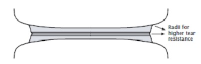
Hinges molded from polypropylene homopolymers or random copolymers, that are not subjected to chemicals or direct sunlight, can be expected to endure an exceptionally high number of folds. The Polypropylene molecules in thin wall sections tend to orient in the direction of the flow, therefore bending perpendicular to the flow of resin results in a strong part that will not break with repeated flexing. Hinge designs have been used in thousands of applications since this phenomenon was discovered in 1957.
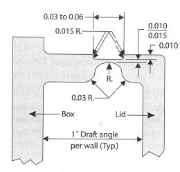
It is important that hinges be designed with the appropriate wall thickness, radius and flat recess to facilitate the appropriate molecular orientation of the material for longevity of the hinge. The thicker the hinge, the more stretching occurs, which leads to cracking and reduced life of hinges. For this reason, the elongation properties and higher tensile strength of Polypropylene are helpful.
When designing a mold for a hinged part, the mold should be made steel-safe and starting with a thin hinge between .008 and .010 in. and then adjusting upwards as needed to a max thickness of .015 in. Thicker hinge sections may be needed, particularly for parts that will be subjected to angular or twisting forces. The inclusion of shoulders in the design allows for increased thickness where the hinge is formed, which helps to prevent bowing of the steel insert. The typical landing length is .060 in. to allow for appropriate back pressure to facilitate uniform melt flow. If the landing is too short or too long the pressure will not be appropriate for proper packing of the mold.
Proper cooling and gate location are essential to preserving the molecular orientation achieved when the mold is filled. Gates should be located in such a way that the mold is filled perpendicular to the hinge plane to facilitate uninterrupted flow as the mold fills, and gates must be positioned to prevent weld line formation and air entrapment along the area of the hinge. It is important that these issues be considered in the tooling design phase, along with adequate cooling channels, which are often considered secondary to other considerations and components. Cooling channels should run parallel and as close as possible to both sides of the hinge to reduce heat buildup.
At I.F. Associates, we offer added value to customers with design assistance and DFM reviews to ensure quality parts and longevity of tooling. Our focus on exceeding customer expectations is consistent and quality and on-time delivery are our top concerns. If you need design assistance for an ongoing project please reach out, as we look forward to helping solve your injection molding challenges.
Email inquiries to: brandy@ifassociatesinc.com
To learn more, you can check out the link below, which includes research on hinge design for extrusion and machining as well as injection molding.
PDF, 206KB